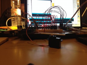
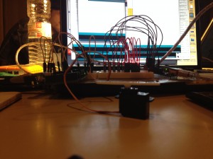
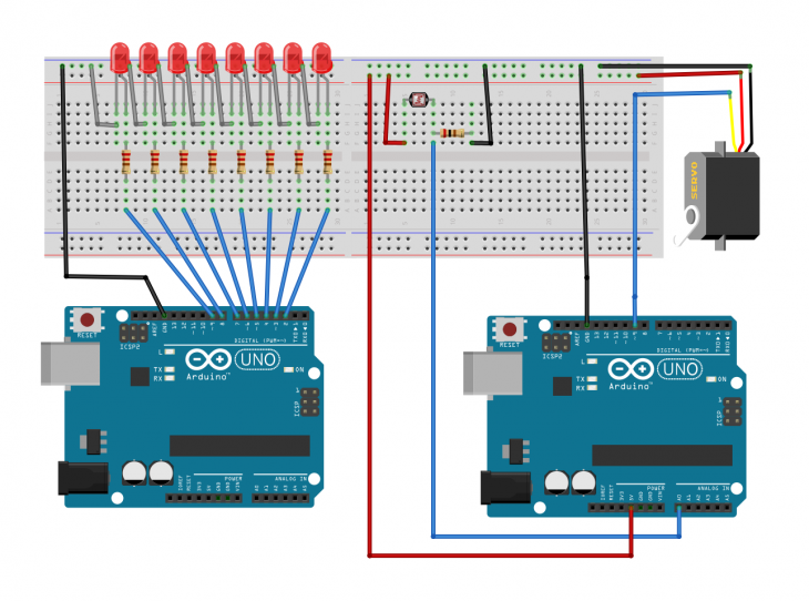
The purpose of this exercise was to control a servo motor with a digitalWrite input. We created a led sequence in one arduino and a light sensor connected to the servo in an another arduino board. The amount of light that the sensor detects triggers the speed and the rotation of the servo. Using two different arduino boards helped us to experiment the distance between the light sensor and the leds which allowed us to have a wider range of servo outputs.
————————————
Analog vs Digital
int led9 = 9;
int led8 = 8;
int led7 = 7;
int led6 = 6;
int led5 = 5;
int led4 = 4;
int led3 = 3;
int led2 = 2;
int brightness = 0; // how bright the LED is
int fadeAmount = 5; // how many points to fade the LED by
// the setup routine runs once when you press reset:
void setup() {
// declare pin 9 to be an output:
pinMode(led9, OUTPUT);
pinMode(led8, OUTPUT);
pinMode(led7, OUTPUT);
pinMode(led6, OUTPUT);
pinMode(led5, OUTPUT);
pinMode(led4, OUTPUT);
pinMode(led3, OUTPUT);
pinMode(led2, OUTPUT);
}
// the loop routine runs over and over again forever:
void loop() {
// set the brightness of pin 9:
analogWrite(led9, brightness);
analogWrite(led8, brightness);
analogWrite(led7, brightness);
analogWrite(led6, brightness);
analogWrite(led5, brightness);
analogWrite(led4, brightness);
analogWrite(led3, brightness);
analogWrite(led2, brightness);
// change the brightness for next time through the loop:
brightness = brightness + fadeAmount;
// reverse the direction of the fading at the ends of the fade:
if (brightness == 0 || brightness == 255) {
fadeAmount = -fadeAmount ;
}
// wait for 30 milliseconds to see the dimming effect
delay(30);
}


