DIS_Workshop_Expanding Structure_Group7

Screen Shot 2015-03-04 at 14.18.18


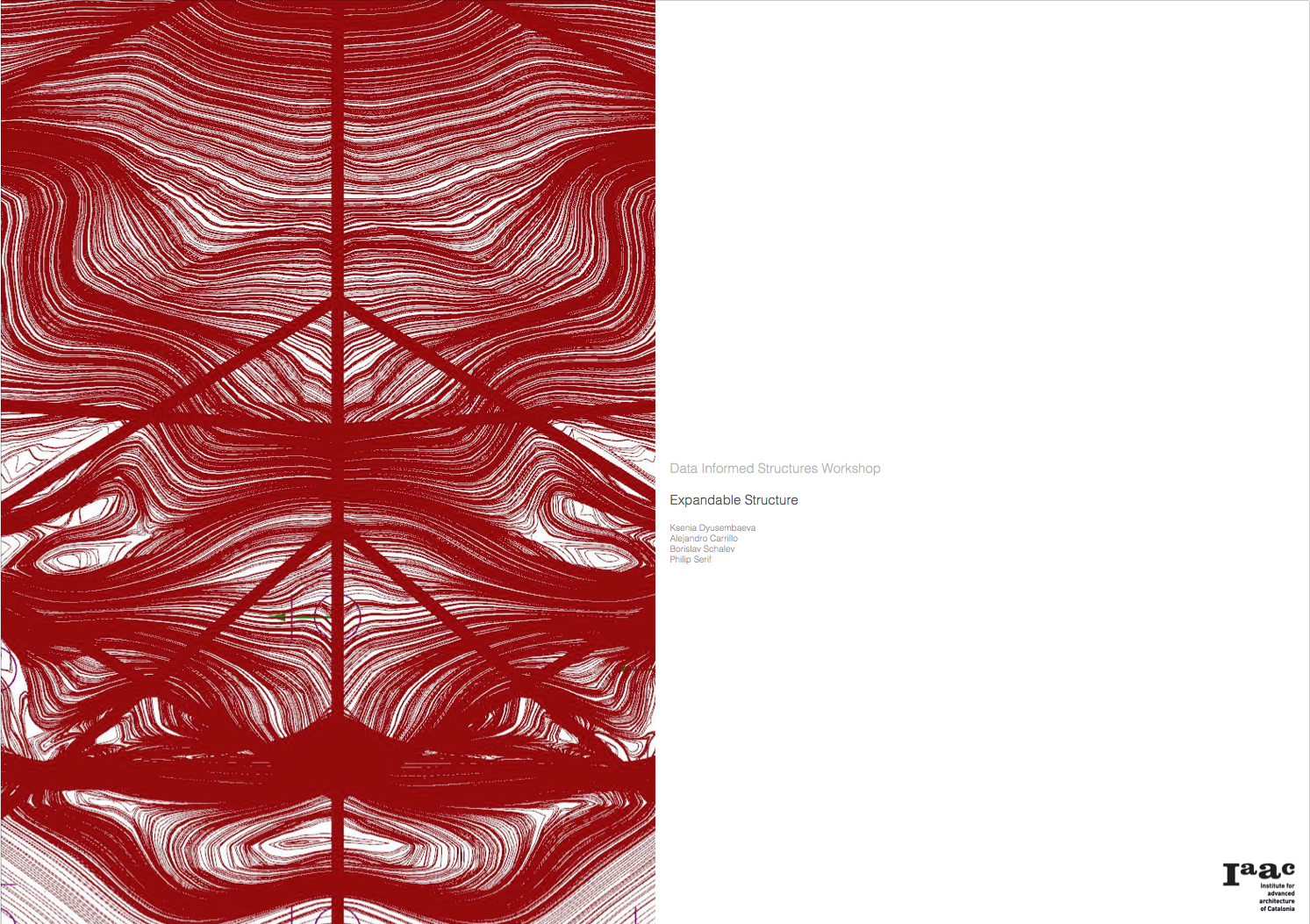
Ksenia Dyusembaeva, Borislav Schalev, Alejandro Carrillo, Philip Serif


Screen Shot 2015-03-04 at 14.18.27

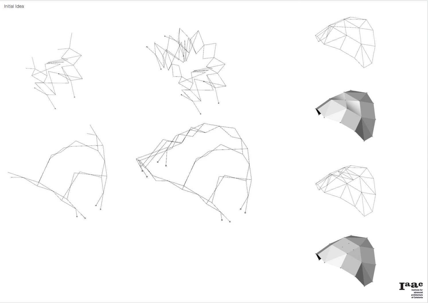
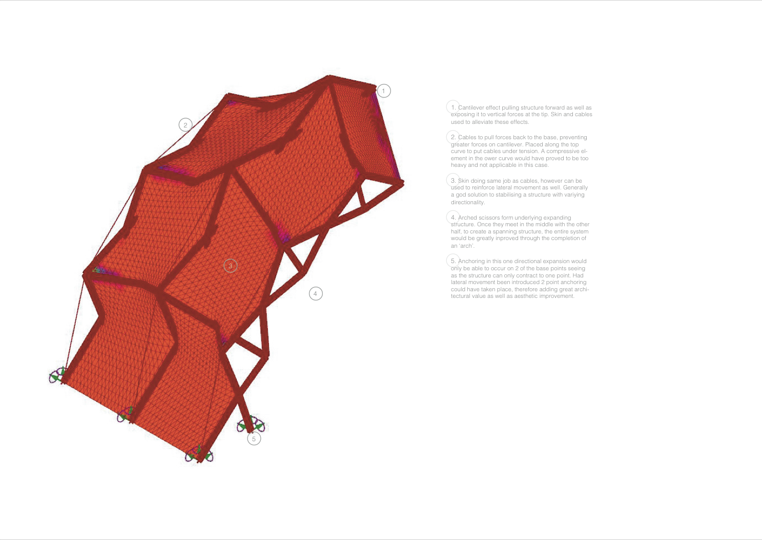
Proposing a lateral/forward expansion structure. Perhaps reinforced by cables and skin systems.


Screen Shot 2015-03-04 at 14.18.37

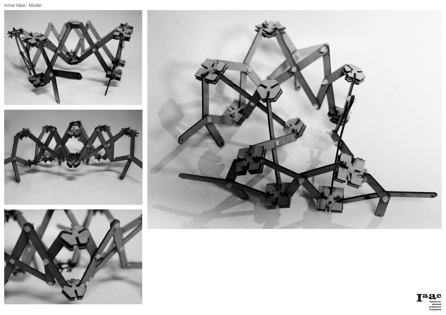
Initial model showing lateral + forward expansion/contraction.

Screen Shot 2015-03-04 at 14.18.48

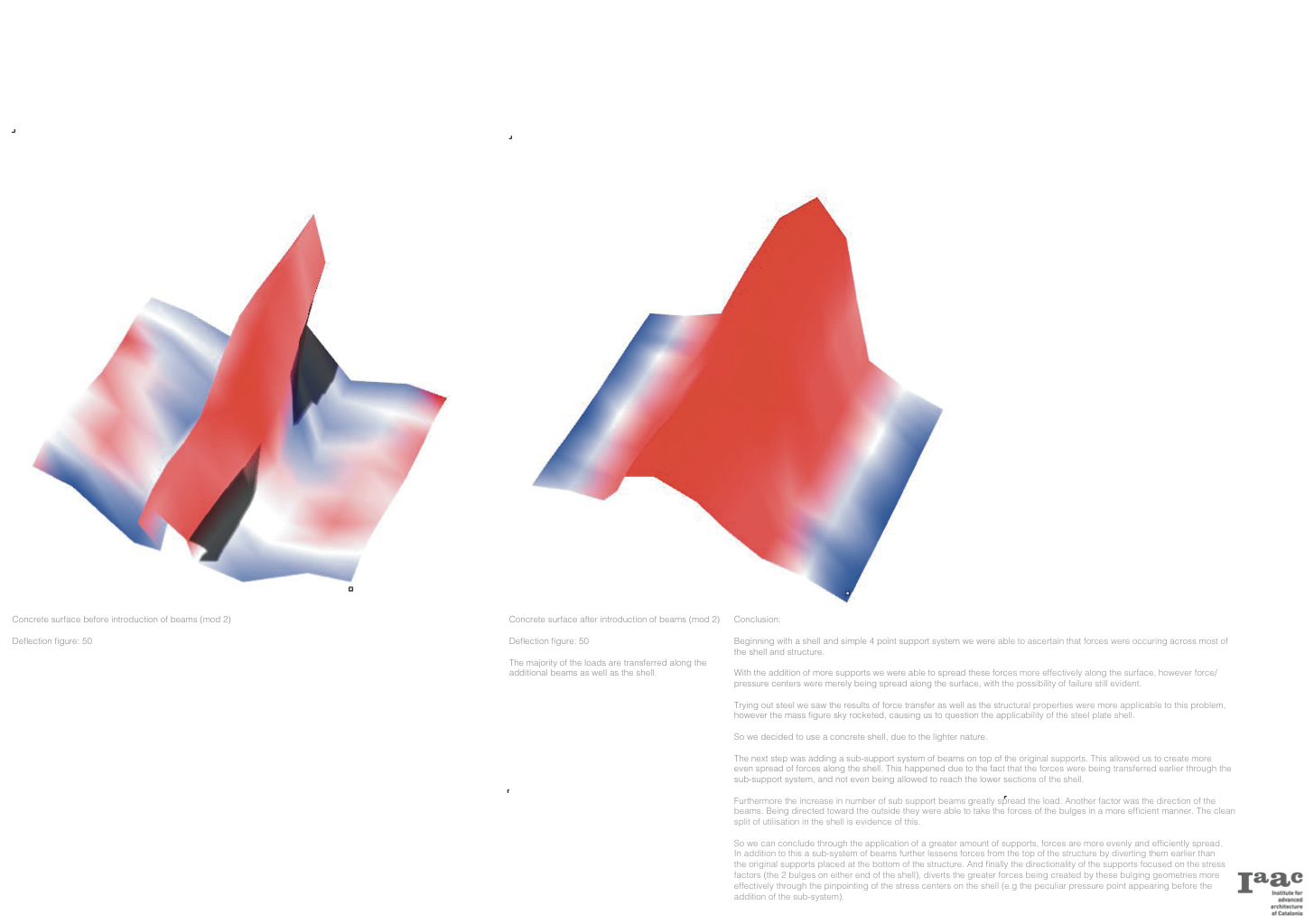
Analysis to ensure greater rigidity in the cantilever, reducing deformation and stresses in general.

Screen Shot 2015-03-04 at 14.20.17

First 3d setup of structural system, exploring effects of forces.

Screen Shot 2015-03-04 at 14.20.25

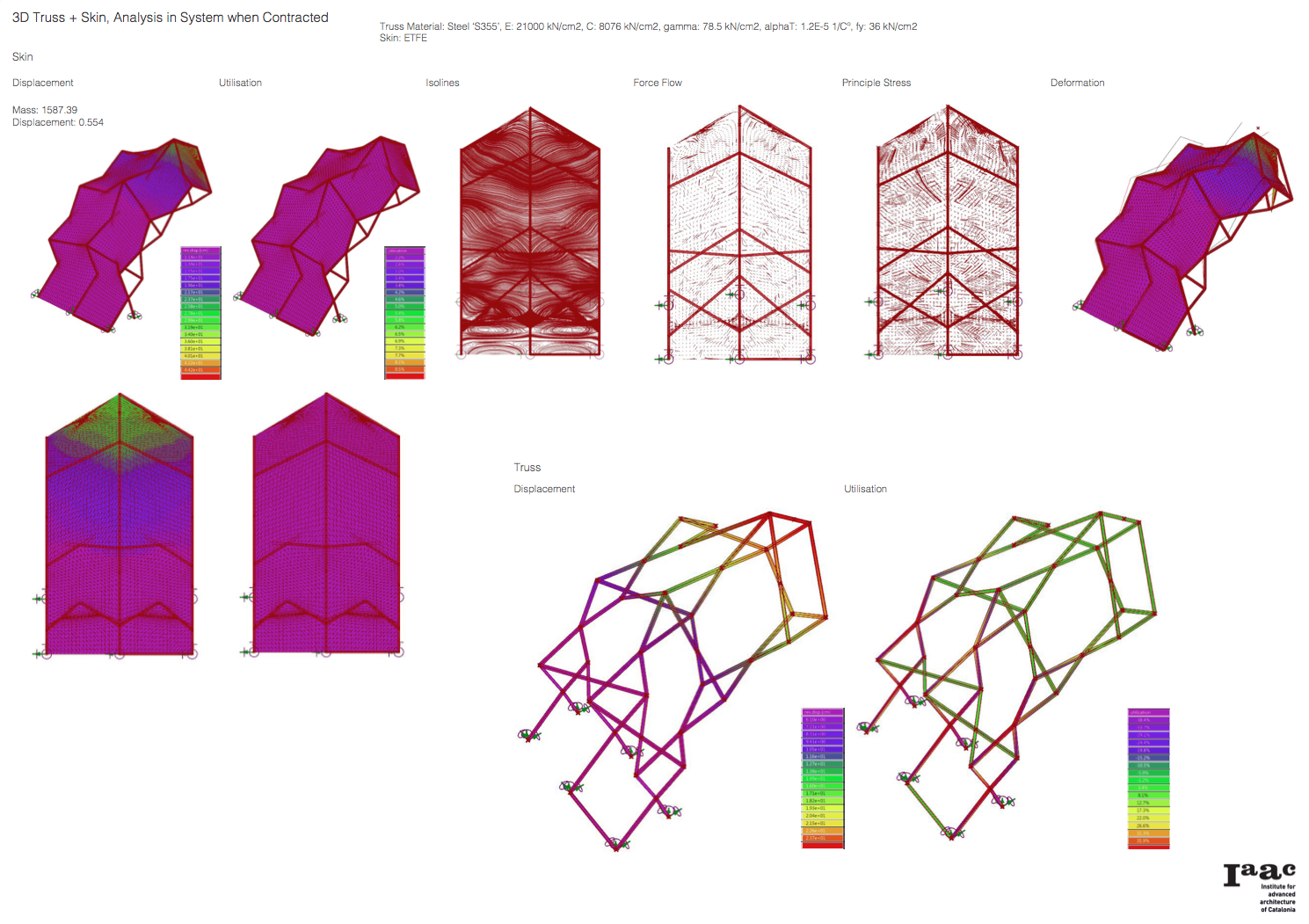
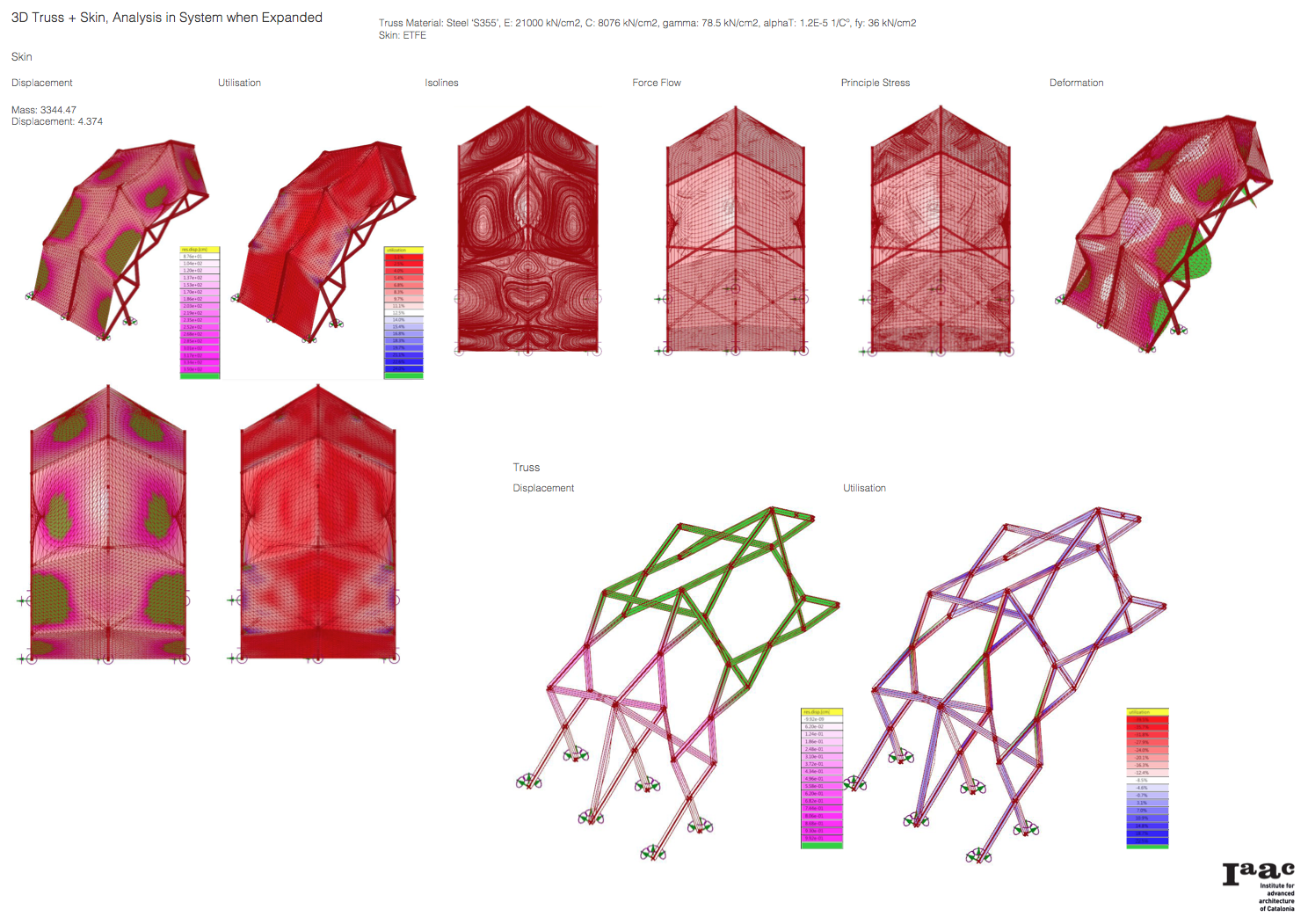
Addition of skin to alleviate excessive forces.

Screen Shot 2015-03-04 at 14.20.38

Screen Shot 2015-03-04 at 14.20.50

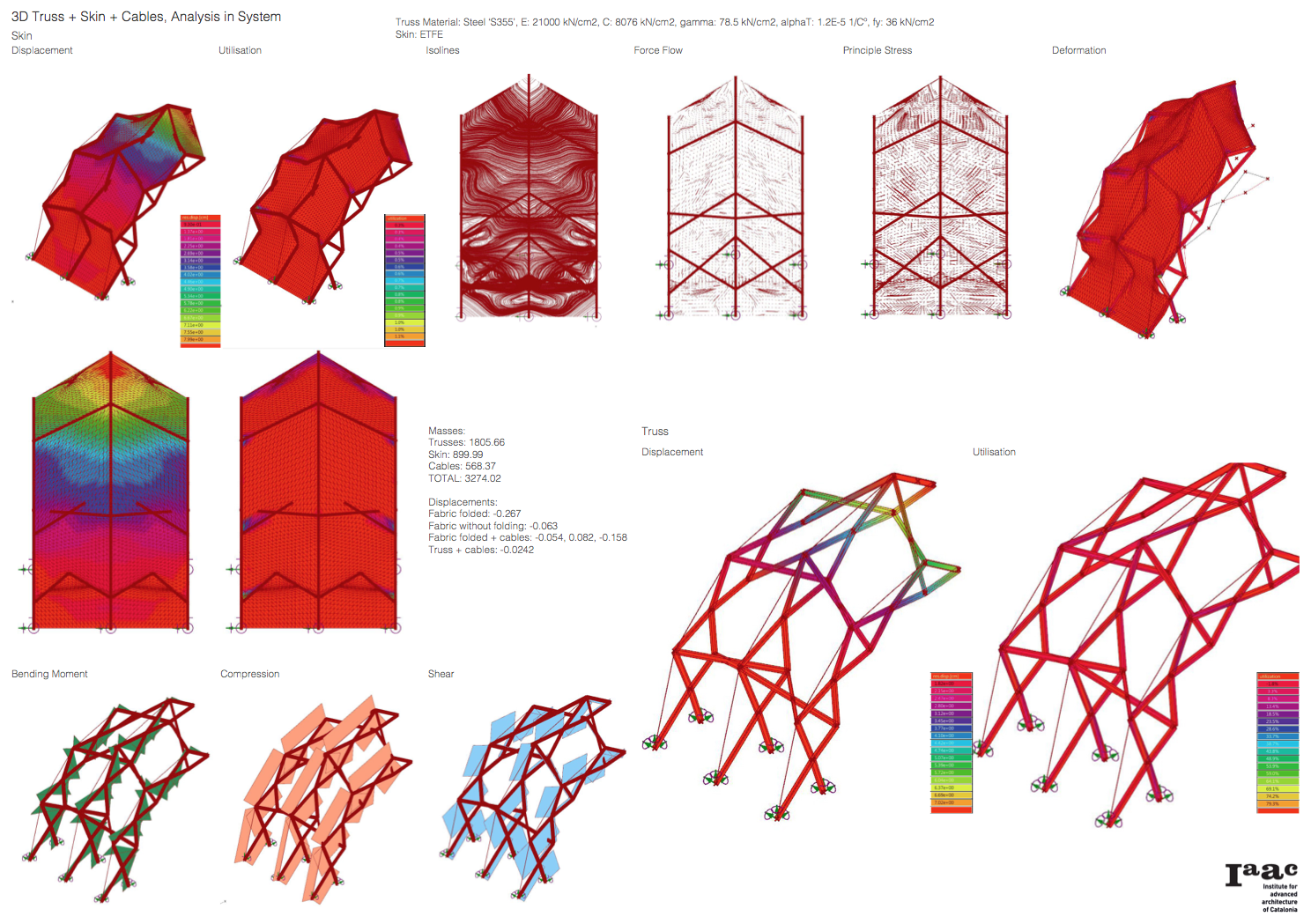
Adding of cables for further increase in rigidity and stability.

Screen Shot 2015-03-04 at 15.32.16

Screen Shot 2015-03-04 at 14.21.17


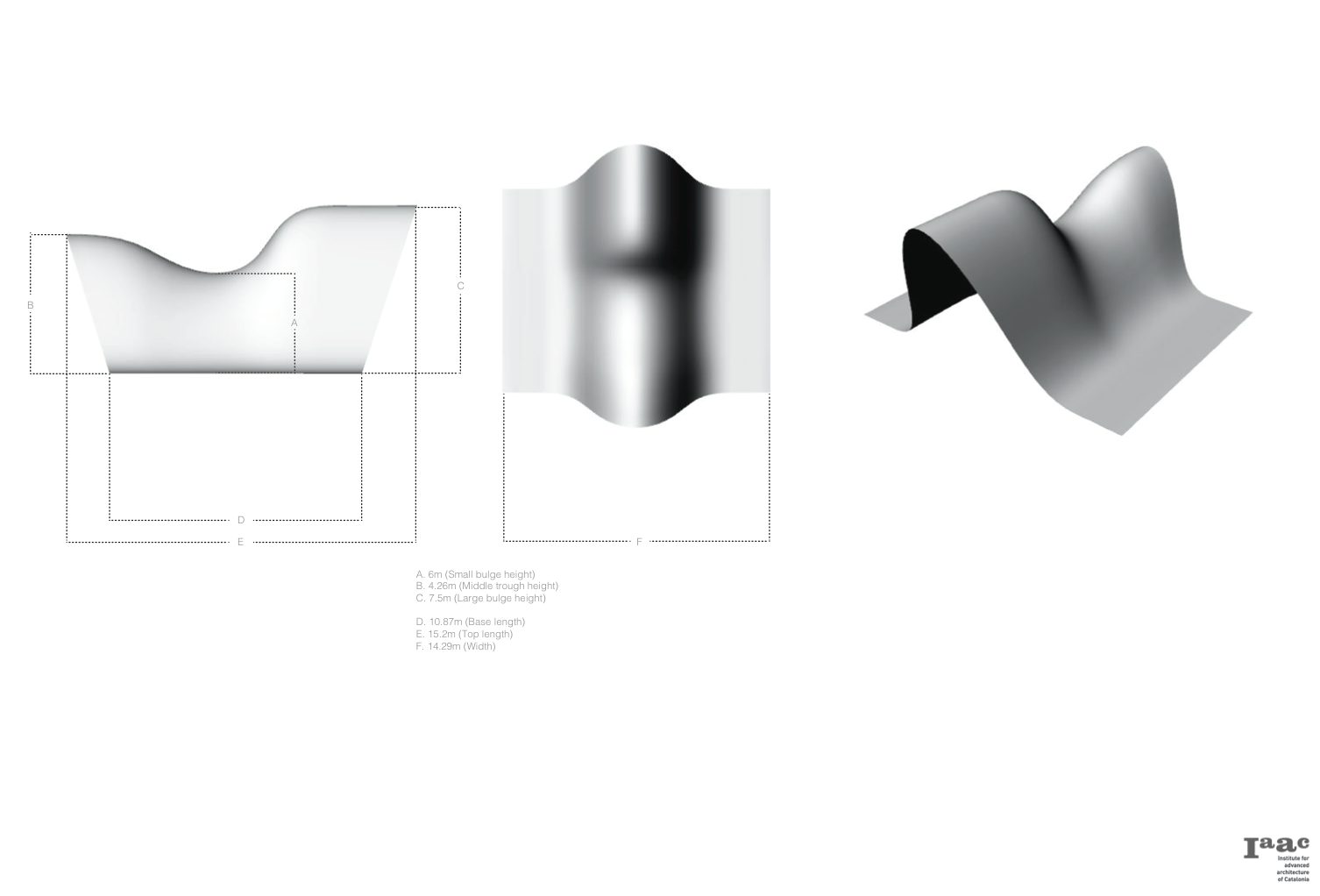
To start with the idea was to create and expanding structure that not only expands in forward motion but also laterally, opening up possibilities for a variety of applications (shelter, bridge, temporary structure, pavilion). This structure would have 2 states; open and closed.

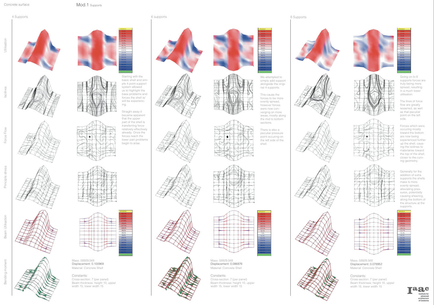
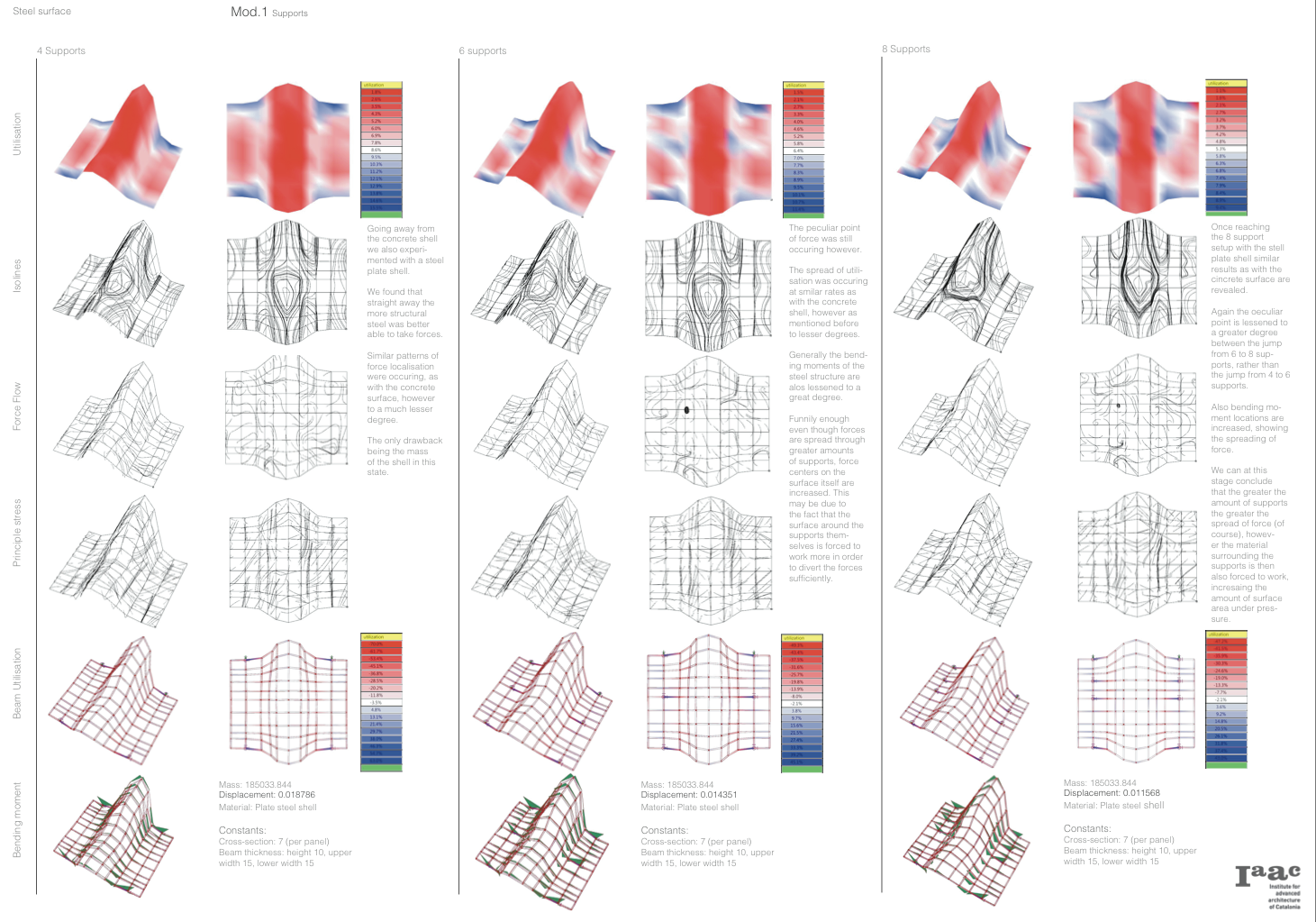
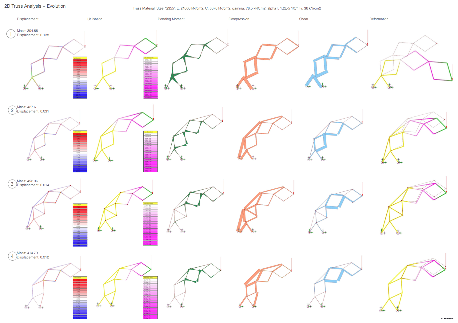
We quickly realised that the forces experienced under such a setup can only be understood once one has analysed the single constituents of said structure. So we simplified the initial analysis down to the ’2d’ truss-scissor system to understand the underlying forces that component experiences. This was important to do since the structure is a collection of these 2d elements.

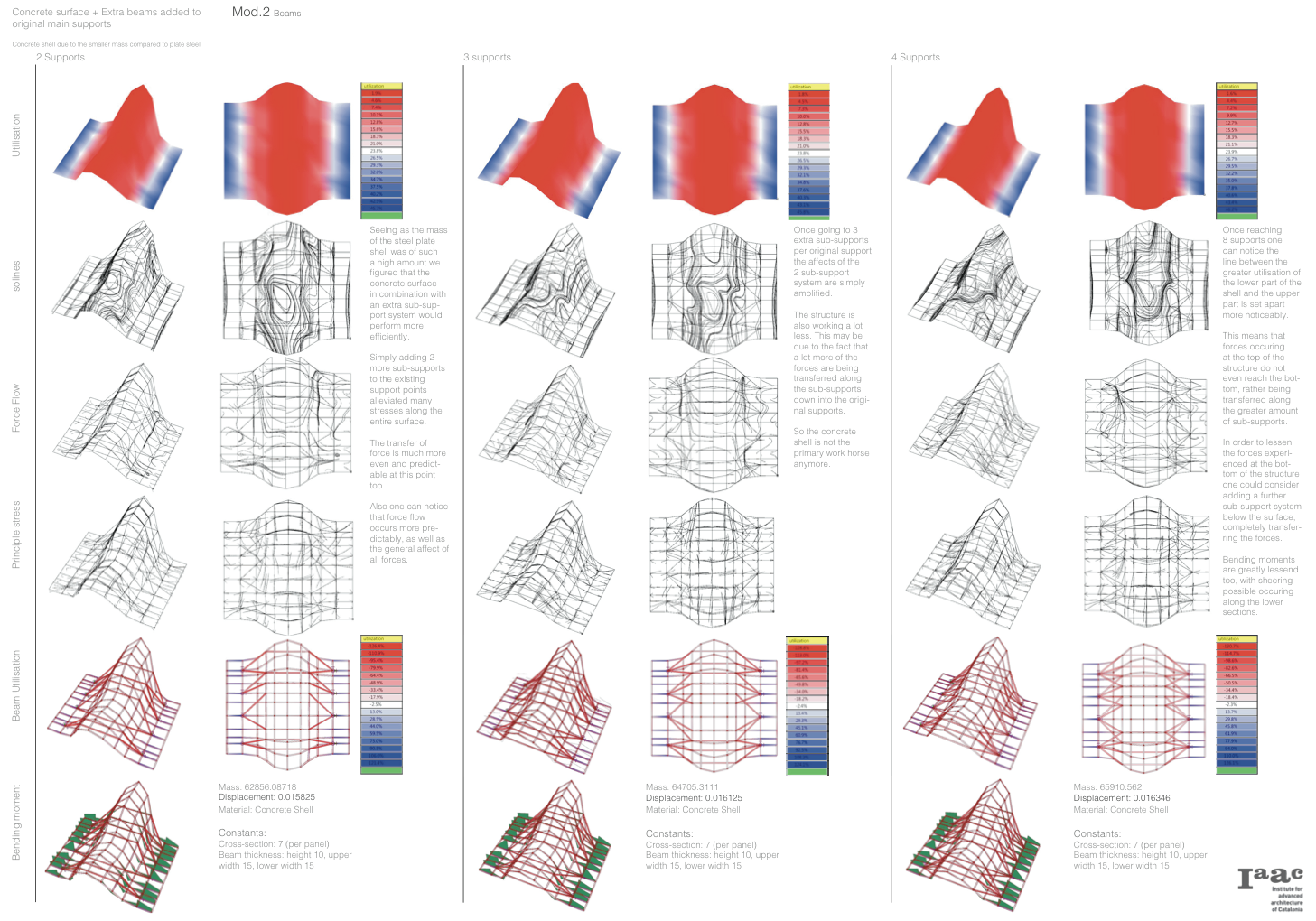
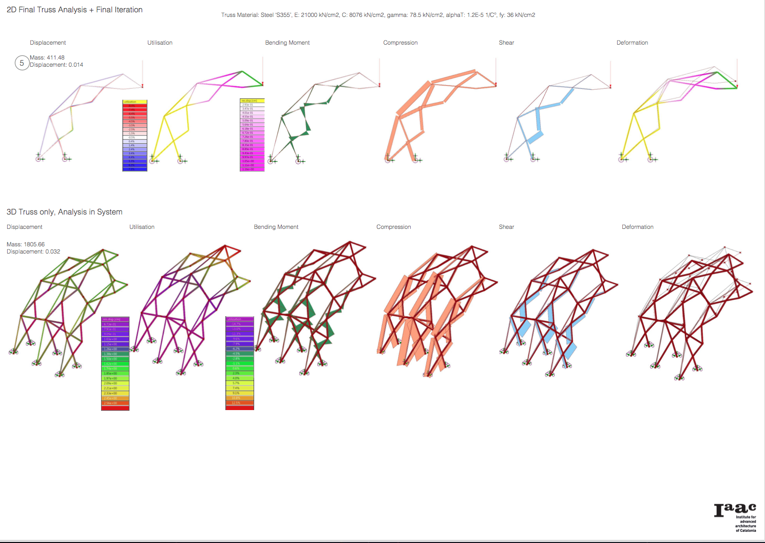
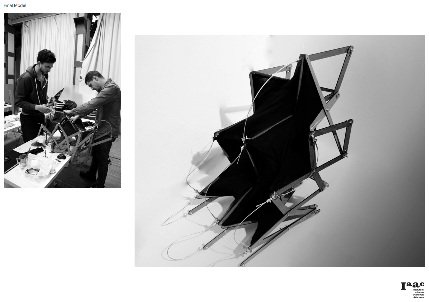
After several analyses the final setup of the 2d truss-scissor was found and we arranged it in a row of 3 of these elements. After extensive study on this now 3d system we were forced to add a skin as well as cables for rigidity purposes, seeing as the structure alone would have been relatively weak, especially when cantilevering in the expanded state.

After ensuring the stability of the cantilever we were going to attempt to create lateral movement as well, however the workshop time expired and we were not able to continue. The problem then would have been to secure the lateral load, leading the forces back to the base.

The next steps would have been to anchor the base points and figure out the lateral movement, which would provide greater coverage/surface area when expanded, and work out a viable method of locking the 2 sides in place once they met at the pinnacle of their individual cantilever effect (creating a spanning structure). Additional, directional specific, cabling would add further rigidity and support for greater lateral expansion. Furthermore a skin may even remove the need of cables if secured in specific spots which would be experiencing the highest concentration forces.

The architectural value/potential of this experiment would have really emerged once the locking of the base and the lateral expansion would have been realised.

Posted in Students | Comments closed

Assignment_03 I Group 6 I Ceren Temel, Samuel Shapiro

DIS_Assignment03_Group6_1 DIS_Assignment03_Group6_2 DIS_Assignment03_Group6_3 DIS_Assignment03_Group6_4

Posted in Students | Comments closed

Assignment 3_Team11_Orion Campos_Prawit Kittichanthira

Shenzhen International Airport

Assignment3 Team11

In Truss Analysis Assignment, we’ve analyzed the truss from Shenzhen International Airport by Fuksas Architects by it interesting aspect of functioning like a shell, but also with main arches through the structure.

We analyzed three sections of the airport, which could represent it structure: An arch with a opening, an symmetrical arch and and an arch with a opening and and an increase of the height in the opening. Each of those arches were analyzed one time, and then modified two times. First, just increasing the number of trusts, and second modifying manually.

In both the cases, the Utilization Graph Analysis, shows that in the middle part of the top chord is the area that occurs more compression, together with the inside part of the arch. The others are basically tension. If the from the subdivision is increased, instead of helping to make the structure more strong we can see that the additional height made the deformation to be bigger. This is show also in the Bending moment graph, where the additional numbers of truss are cutting more the structure And this show in the Bending.

At the second modification, with the manual addition of elements on the arch on specific areas where it was most needed, it helped much more the structure, since the weight didn’t increased much more (seeing on the deformation graph) and it showed a better result on the utilization graph.

The main differences between the three types of section is that the symmetrical one was better, presenting a more homogeneous change on the normal force and the bending moment, than the most asymmetrical ones.

Posted in Students | Tagged | Comments closed

Assignment_3_Group2_PhilipSerif

Screen Shot 2015-02-18 at 01.26.37

Screen Shot 2015-02-18 at 01.27.24

Screen Shot 2015-02-18 at 01.27.39

Screen Shot 2015-02-18 at 01.27.55

Screen Shot 2015-02-18 at 01.28.09

Screen Shot 2015-02-18 at 01.28.18

Screen Shot 2015-02-18 at 01.28.30

Screen Shot 2015-02-18 at 01.28.39

Posted in Students | Comments closed

Assignment_2_Group2_PhilipSerif

Screen Shot 2015-02-18 at 01.24.28

Screen Shot 2015-02-18 at 01.24.41

Screen Shot 2015-02-18 at 01.24.54

Screen Shot 2015-02-18 at 01.25.05

Screen Shot 2015-02-18 at 01.25.15

Screen Shot 2015-02-18 at 01.25.29

Posted in Students | Comments closed
  • Students

    No sub-categories

  • Archives