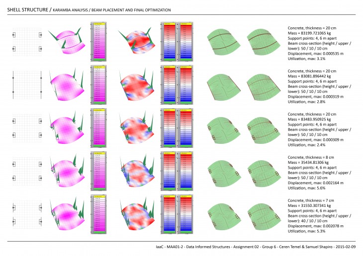
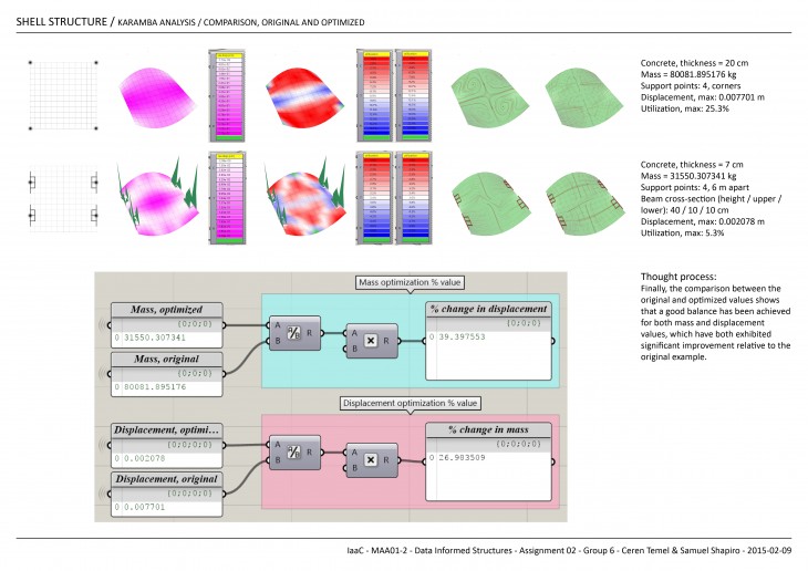
Assignment 02_Group 6
Excerise 2_Team11_Orion Campos_Prawit Kittichanthira
Analysis
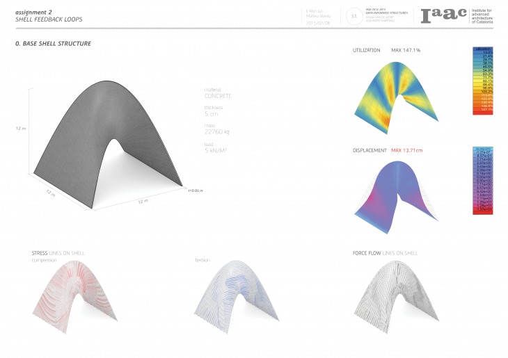
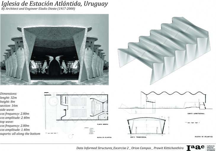
The building is already extremely efficient. It is made by traditional construction bricks which are generated from two lines and three cosine curves, two of them in the XY plane and the top one in the XZ plane.
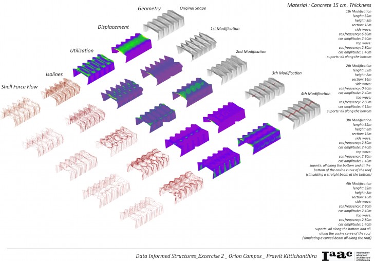
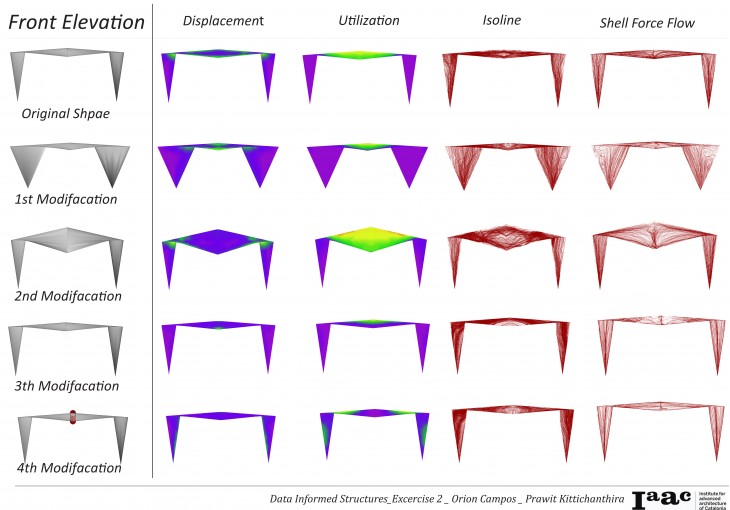
The utilization graphs show how smart the form is, since the roof, which is the weakest part of the structure (clear at the displacement graph), was folded to distribute the stress among all the surface. At this graph is showed that the folding edges of the roof are the more stressed ones, due to their horizontal. The Forceflow graph show how direct the building conduct the forces to the ground.
The aim of the first modification was to decrease the utilization of the edges of the folded roof, by increasing the amplitude of the lateral curves that generate the building. This was achieved and also was the almost total elimination of the displacement along the roof. In other hand, the forcelines became more curvy, due to the increase of the surface area at the folding walls, which caused the forces to travel in a bigger path.
The objective of the second modification was the same as the first one. This was made increasing the amplitude of the cosine wave of the roof. This modification also decreased the utilization of the roof, but concentrated it near the edges. Also, couldn’t be as efficient of the first modification in the decrease of the displacement, and the middle of the roof continued to be the region with the biggest movement. The only advantage from the first modification is that the shell force flow has a more fluid path.
At the third modification, it was inserted a series of supports as points at the bottom of the cosine curve of the roof, maintaining the original dimensions. This was to simulate a straight beam under the roof. With this support, the main displacement moved from the middle of the roof to its edges, and decreased the utilization of the structure, but maintained at the points in which the surface would touch the beam. Also, this additional beam created two new force flow paths at the roof.
The final modification is a variation of the third one, but instead of a straight beam, it was created supports simulating a curved beam located at the cosine curve at the top. Those supports also helped to divide the most fragile region of the structure, dividing it at two lines, along the roof. This is clear at the displacement, isolines of displacement, and shell force flow graphs. One interesting factor is that since the utilization of the roof was balanced, the inner edges of the folded wall became the most utilized areas of the structure.
