Sheet rubber has two properties that are uncommon in structural or architectural materials.
1) “Stickyness:” rubber with a glossy finish sticks to other rubber surfaces, amplifying friction
2) “Springback:” rubber has a high degree of elasticity, allowing it to spring back to its original shape when released from deformation or stretching
SINGLE COMPONENT
TWO COMPONENTS ASSEMBLED
This component is based on the following studies of material properties:
STUDY 1
Rubber can be molded into various native surface geometries; it doesn’t need to be in a flat sheet.
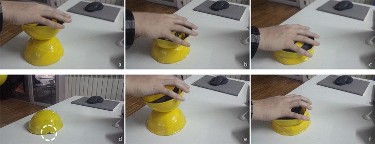
In study 1, two hemispheres of rubber are equal in dimension and shape, but (regardless of which hemisphere is positioned above or below the other) the same one always deforms when the two are compressed together. The deformation occurs in the hemisphere with a small notch cut in the rim (slide d). This small change is sufficient to make the geometry of the hemisphere less stable than its counterpart.
STUDY 2
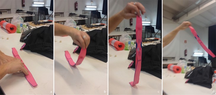
In study 2, there is no adhesive or fastener, the material is simply pressed to itself. The friction between the material holds it in place, even when swung.
STUDY 3

The same principle is applied here as in study 2, but in this case the stickyness and the springback act together to hold the center strip of rubber in place. The springback of the strips puts sufficient pressure on the neighboring rubber to enable friction.
STUDY 4
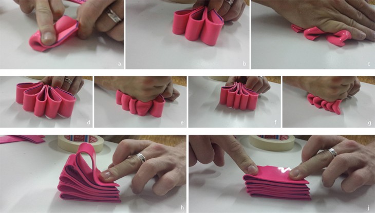
Study 4 investigates strategies to use the stickyness and springback to lend more structural rigidity. In slides a – c, the material does not have enough rigidity to resist deformation. In slides d – e, the additional components are much more resistant. The radii of the loops of material are also important here. In d – e, the radii are larger (and therefore the strips have wider spacing) than in f – g. F – g is less resistant to compression, as the strips are close enough together to all deform as one.
STUDY 5

In study 5, the stickyness between the rubber components (combined with a geometry that increases pressure between the two layers when they are pulled apart) holds them together under tension.
STUDY 6
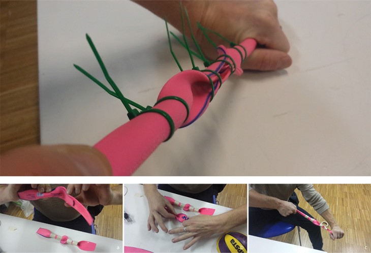
Using the same principles explored in study 5, strips of rubber are assembled in a geometry that will increase surface pressure between layers when the components are exposed to tension. The material is held together with compressive rings; the assembly does not require adhesives or pierced fasteners. This creates a rubber muscle, as the material can resist a high degree of tensile force, and then springback to its original geometry (without any permanent plasticity deformation). The more surface area of contact between sheets of rubber, the stronger the connection.
STUDY 7
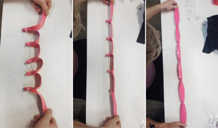
Study 7 tests the behaviors illustrated in study 6, with a different style of connection between strips. In this case, the tensile forces are pulling perpendicular to the center axes of the compressive rings, rather than parallel to them. This connection type is much weaker than the type in study 6.
STUDY 8
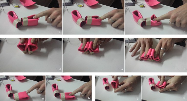
Springback is explored in study 8. When compression is applied along the face of a folded rubber sheet (as in slides g – k), it compresses fully to the thickness of the material, at the point of applied pressure. The areas directly around the pressure points are slightly more expanded. When compression is applied along the rim (as in slides a – c), due in part to the geometry of the folded piece, the material deforms to approximately halfway between the table (the limit of its possible deformation) and its starting point.
Two loops compressed simultaneously (slides d – f) can act as supports for each other.
STUDY 9
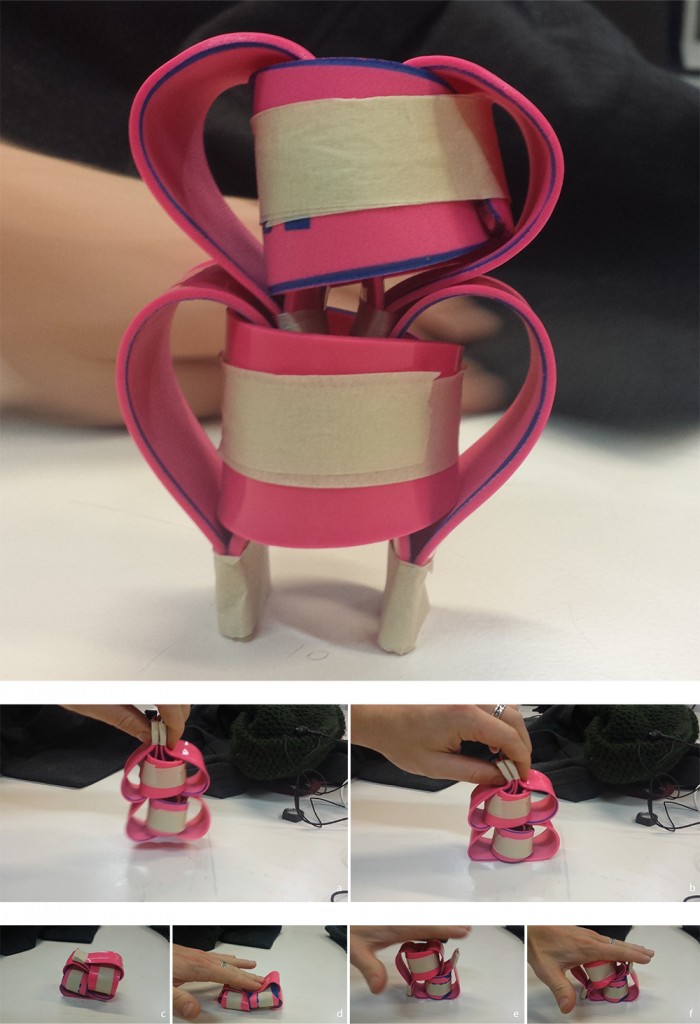
This study explores a component comprised of material looping both horizontally and vertically. The springback pressure and stickyness of the rubber allow the component to aggregate stably. When the component is compressed on the rim of the loops, it is much more rigid than the loops in study 8, implying that multiple strips with a high degree of surface area contact (study 9) are more stable than one sheet of material folded over itself (study 8). When the component is compressed on the surface of the loop, it deforms to the thickness of the material at the point of applied pressure, just as seen in study 8.
STUDY 10
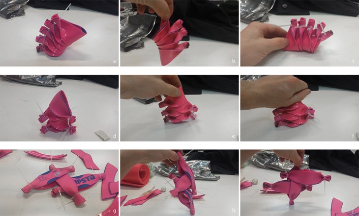
Study 10 looks at how discrete components can be aggregated by fitting into one another. The components shown in slides a – f resist deformation, but aggregate according to the thickness of the material; the result is rigidity from mass rather than from geometry or from material properties.
STUDY 11
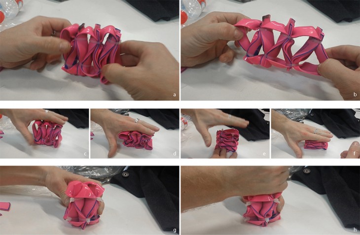
Study 11 shows rubber components that are aggregated with their neighbors via compression rings. The components can resist both tension and compression (slides a – d). This is due in part to the aggregation method and in part to the material properties. When the same geometry is arranged radially rather than linearly (slides g – h), the resistance to compression increases, due in part to the increased mass of material beneath the point of applied pressure. In the tension direction (slides e – f) the components deform to the thickness of the material when exposed to compression.
