Beat Glove Proto_2- Wifly Osc

P1015305 from rafael vargas on Vimeo.

P1015315 from rafael vargas on Vimeo.

Glove osc Update from rafael vargas on Vimeo.

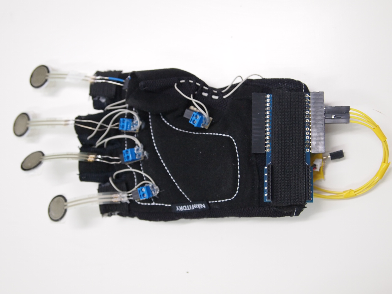
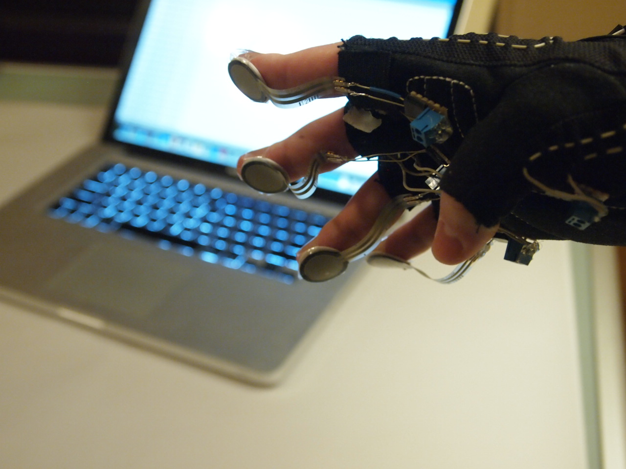
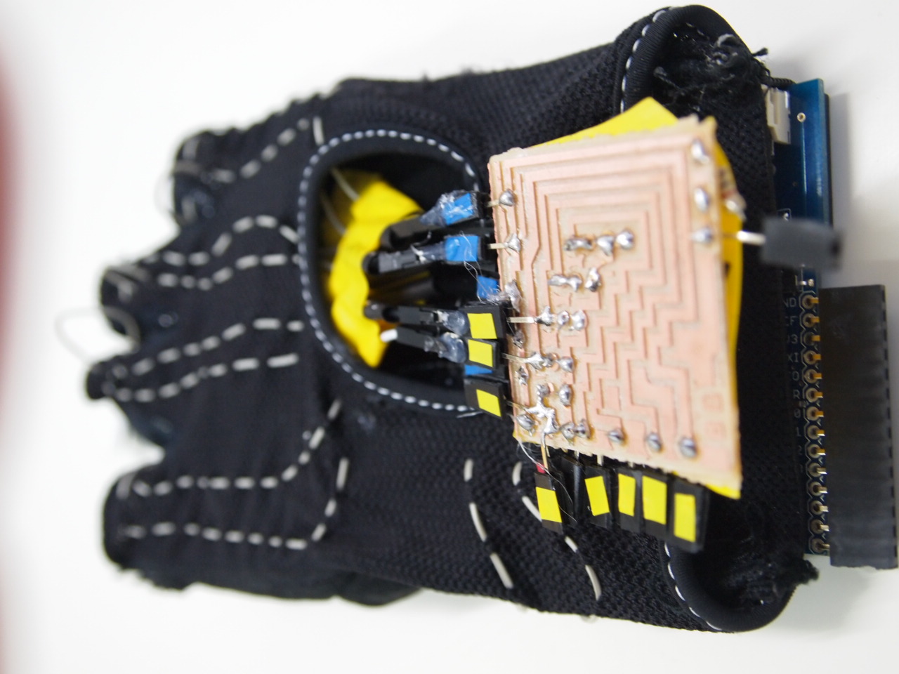
The drum gloves comes from the idea of converting movements and sounds from physical and electronic instruments into a portable ‘surface free’ sound producer. Instead of hitting a specific surface with your fingers that outcomes in some type of sound, the  drum gloves will provide you with surfaces will be on your fingers. The concept is that when you wear the gloves, you can hit any surface and produce midi signals that can be sent to your mobile phone, tablet or computer and use any virtual instrument. Assign some instruments and start playing.

Changes made for the final

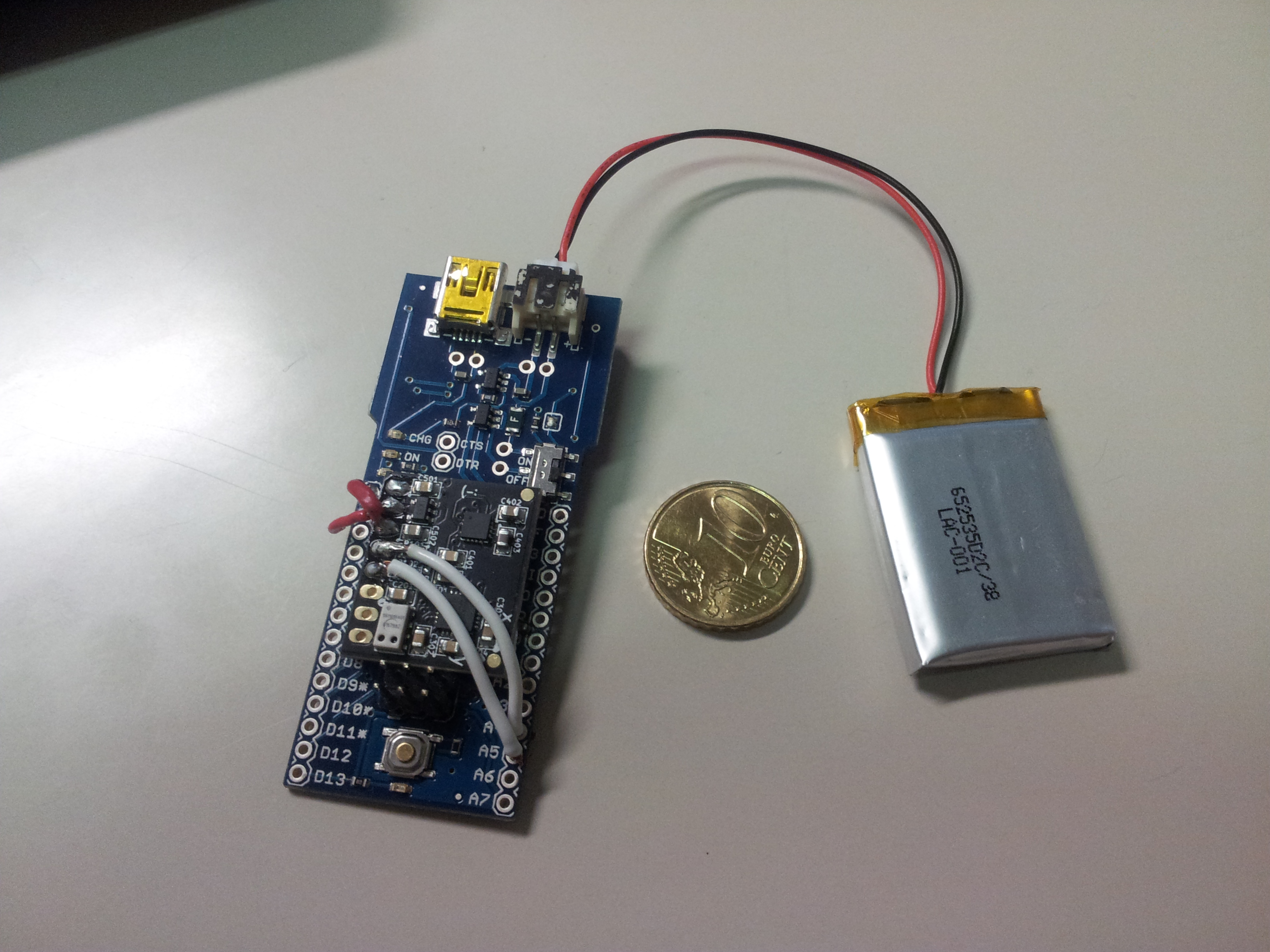
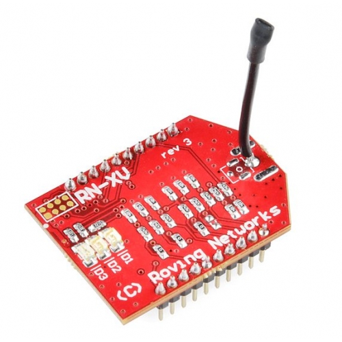
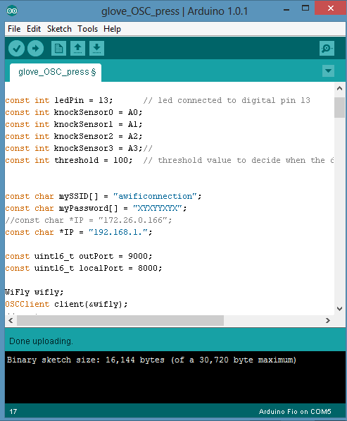
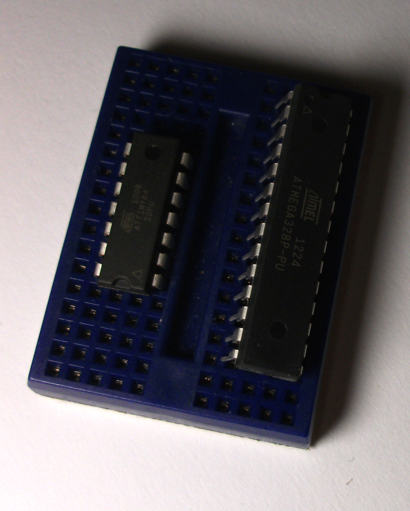
Smaller components were needed. Also to get rid of the cable that goes to the computer. Arduino Fio solves those problems. It’s small and you can connect a 3v lithium battery to it. The wi-fly adds the capability of communication via Osc Protocols with any device that can handle it: Computers, tablets, mobiles. . .

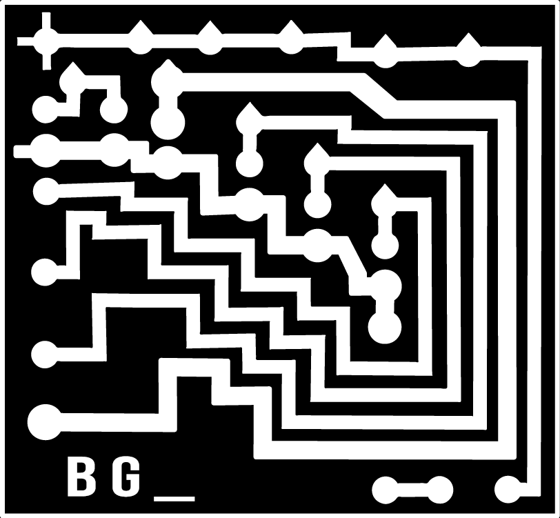
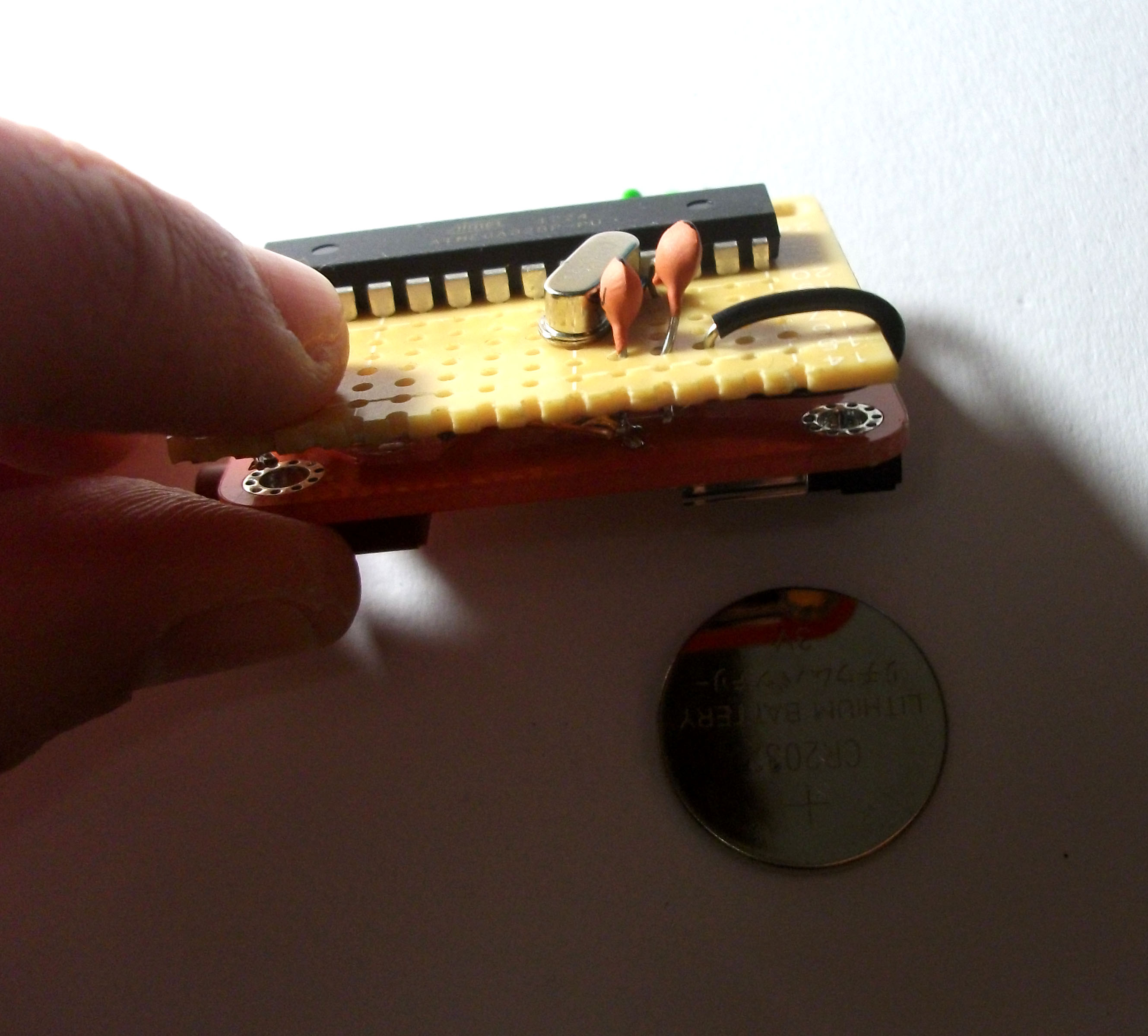
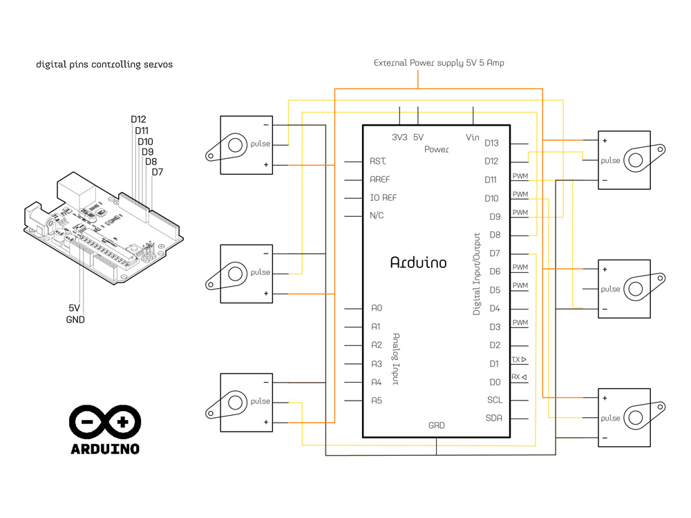
Now, this time the prototype needed a smaller circuit board because the glove is smaller. A custom circuit board was milled @ the fablab for that.

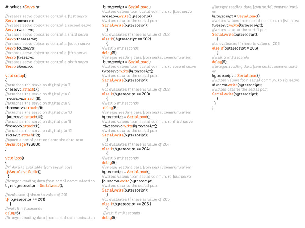
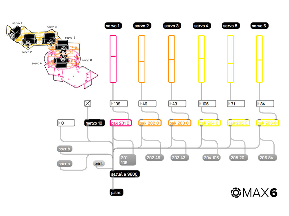
The code got a lot more complicated than with the waveshield. Osc packets had to be send via wifi using the ip addres of the device that was going to be targeted. To test messages were sent to max msp. These messages  had to be activated  by the pressure in the finger sensors.

Posted in Physical Computing, Rafael Vargas, Students | Comments closed

Live Radio –Phew!

OK, so I have been developing the work around the live radio over the last month. When I say last “month”, you assume that I am now done with three radio projects instead of one, but unfortunately, that’s not quite the case. My main interest in this project is to create a complete system composed of sound transmitters and receivers that are mobile and work efficiently together.

I have been following the checklist I set for myself on the last post, which starts by shrinking the circuit. Before I start, I should tell you that I did a lot of miles in this project. Distance miles. Went to the airport twice to pick up my DHL shipments, where in theory I paid for a door to door delivery, then ended up skateboarding between airport terminals. :)

Back to shrinking the circuit, I ordered AtTiney84 from Farnell (and picked it up from UPS office in Hospitalet!). The pieces are really tiny as you see on the left of the right picture, but they don’t support all arduino functions, which is what I discovered after getting them. Of course! So my other alternative was to use the Atmega328P, which is the same chip of the arduino.

uploading sketch to standalone chip

Board and shield I don’t have enough expertise in any of these details, but the web is a blessing. Check MIT references here and and arduio pages. So, I burnt the bootloader for the new chips using 2 arduinos, then wired the chip on a breadboard and uploaded sketches using arduino as ISP. Those are very interesting and cheap methods (since we don’t use and external programmer) for programming the chips. Then I tested the transmission pieces with the receiver pieces and they work together perfectly. For a newbie, that was a lot of learning and loots of troubleshooting! But awesome, now I can save size and money (the chip is 2.5 EUR while an arduino is 25 EUR! –big difference) and run the piece independently using 2 (3V) batteries. So that operation is done and tested, I needed to complete soldering the standalone board with the FM shield, and pack this is a nice 3D printed casing.

Quick render of the case


The printing thing took me over a couple of days of troubleshoot, and logistic problems, and other random stuff, so for the final presentation, realistically, I don’t think I will be able to finish those pieces (still need to solder the boards as well!), but I made a quick up mock up using polypropene, to give an idea of how this should look like notice the parabola at the microphone outlet, I would like to test this idea in the future using different geometries and materials.

Unfinished 3d prints

So for the demo, I guess, I will build a unit for the receiver, and keep the transmission units arduino dependent, just to illustrate the idea. I would have loved to finish everything . . . but time is fast. :)

Reception unit

Posted in Moushira Elamrawy, Physical Computing | Leave a comment

Final-Project Jumobj

The idea for the final project is the make an object that jumps that’s why the name JUMOBJ.

So we have a tetrahedral as our shape. I chose this shape because opposite to every surface there are corners. So i used this arrangement of a form as my input and output. So I have a light sensor in the center of each surface as an input  and use the corners of the form as an output device that makes it jump.


So now lets look at our piece in detail. We are using Solenoids as our push actuators, light sensor as input. Here is a list of things that we used.

Arduino board
• USB cable for programming and powering the Arduino
• Breadboard
• Some jumper cables
• A 1K resistor
• TIP120 transistor (TIP102 will also work fine)
• 1N4004 diode (1N4001 also works)
• Some batteries and connectors for solenoid power
• A solenoid with leads to connect to the breadboard

Circuit board

So we have  four surfaces for light sensors and four corners for our solenoids to push the object. In order for the solenoids to push  it needs a transistor to amplify the current from coming from arduino.  When the solenoid is in action it act like generator for the short while. Is action can damage our circuit. So in order to prevent is we use a diode.   For the light sensor it needs a resistance connected in parallel to the input pin and ground. below is the  curcuit schematic.


Solenoids in Action

So the only small workable 12 volt solenoid that I found were a pull solenoids. So i had to convert them by inserting a nail into the pulling pin the welding a nut to the nail on the other side.


Construction of  Piece

All the components are laser cut.Below is the image that explains it in detail.


The mean concurne was will the solenoid be able push the object hard enough that it looks like that it is jumping and which type of solenoid would be best for this job. Since we didn’t make the piece  so we didn’t know it’s weight & we did’t want the object to be really big and heavy.So there was an trial and error method to figure out if it is going work at all or not.

And so far it is still in work.

Posted in Furqan Habib, Physical Computing | Comments closed

Personalized Live Radio

The idea of this project is to simply create audio capturing unites, that transfer sound over FM. Using multiple transmitters, we create a receiver device that acts as an output for different audio channels, and which also has a mixer. I would love to add recording functionality as well, if I managed to. Below is a diagram illustrating the simple system architecture:

My initial thought was to capture and manipulate live outdoor sounds (tree leaves, car wheels, ..etch) however due to sound quality and signal transfer of FM available ranges with this shield (50 ~70 m). I am now testing with capturing unpredictable sounds, from very close objects.

Below are images from testing the transmission from a tree as well as testing for different sound reflection techniques:

Right now, I need to:

1. Find a better way to design a compact transmission unit that is small, independent, with good powering solution (one option is to use Arduino Fio and Lituhum battery , another even more compact option is to use ATtiny85 chip

2. Define interesting sounds for personalized channels

3. Make sure the analog mixer will actually work nicely with these generated sounds (I really want to rely on a variable resistance technique to change sound, without using any interface)

4. Amplification, if needed..

If all the above went well, I should be able to finalize it and build the radio :) — you just need to wish me good luck!

Happy Holidays :)

Posted in Moushira Elamrawy, Physical Computing | Comments closed

Final Project / Robotic Arm

For my final project of physical computing I decided to build a robotic arm, controlled by
six standard-sized servo motors. The idea was to control servos of the robotic arm with an
arduino code, using a serial communication with a bunch of different softwares such as
Processing or Max MSP.
As a basis for building a robotic construction I used an open-source  robotic arm from
Oomlout. The structure of the robot consists of 26 parts, which need to be laser-cut, either
from a 3 mm thick wooden panel or an acrylic glass sheets. Parts are then assembled, using
3mm screws and nuts.
materials required: 3mm thick sheets of acrylic glass or wood, screws and nuts (3mm),
electronics: arduino board, breadboard, jumping wires, servo extension cables,
6 standard servo motors (4.8-6V, 6 kg/cm, 40 grams), external power supply for servo motors
(25 W, 5V, 5 Amp)
software: Arduino+servo library, Max msp (for serial communication and control interface )
other software possibilities for serial communication and servo control: Processing, Open CV…


Posted in Martin Lukac, Physical Computing, Students | Comments closed