Category Archives: Students

3D Printing – Soma Cube

Concept:

The concept of the joint was conceived to generate different features in a single element instead of just having a simple joint. We try to play with speculation and with these criteria we are looking for unpredictable results. The joint features promote the application of different types of rotation and movement in 3 axes. One typology of joint can also be combined with other typology in order to create a different joint.

Function:

The functionality of the joint is defined by the typology of each element. Each joint is consisted of two, three or four cubes. To assure connections between the joint and the bars, each cube has two to five holes for putting the bars. The location of each cube is defined by its 360 degree rotation, according to necessities. The joints can also move along the bars.

Wherever it´s needed the joints can be combined therefore it´s possible to attach bars as much as wanted. Another features is that the joints without bars can be a Soma Cube, an unpredictable structure.

Also posted in IC.1 Digital Fabrication, Noor Alain Ahmed, SEIICHI EDUARDO SUZUKI ERAZO | Comments closed

3D-Slidate(Slide-Rotate)


We wanted to create a set of joints that would allow our structure to expand and shrink, move in every axis and in the same time be able to connect with another module so it can be populated and create a dynamic surface. The geometry we used is based on two hexagons, one nested into the other connected only in three points. The inside hexagon can vary the length of its sides and the angles between them while moving in every direction when the outside can only vary the angles between the sides. The assembly can be tiled in two dimensions and can possibly create a lightning system or a performing façade.


1st joint –Characteritics -1 connection that permits sliding on a bar, 1 connection that permit 3-axis rotation
Geometry –One internal sphere with a hole for sliding and one external ring with a joint that car slide on the sphere offering 3-axis rotation(restricted by the bar that slides on the sphere)
Functionality – forms the internal part of our structure and allows movement to every direction

2nd joint -Characteritics -1 connection that permits sliding on a bar, 2 connections that permit 3-axis rotation
Geometry – One internal sphere with a hole for sliding and two external rings with joints that can slide on the sphere offering 3-axis rotation(restricted by the bar that slides on the sphere and the interaction between this two rings)
Functionality – forms the external part of our structure and allows movement to every direction

3rd joint –Characteritics -4 connections that permit two axis rotation
Geometry – Four different layers of half rings that can rotate about a central axis. On each ring there is a joint that can move along its length
Functionality – forms the external part of our structure and allows movement to every direction

Also posted in Akram Ahmed Salah, Aron Biro, IC.1 Digital Fabrication, Pavlos Bakagiannis | Comments closed

MILLING: CONTRAST


In this milling exercise we tried to create a panel that would show the contradiction between a smooth surface and a more machine made- industrial set of drilled points. We used a surface as the starting point and on it we traced a set of irregular curves that went through only the first layer of our valcromat panel. For this first strategy we selected the 54mm ball mill in order to produce a rather smooth surface at the boundaries of our curves. Moving on we selected a second set of surfaces and from these we produced points that we then used for our second strategy. This time we used the 10mm flat mill and we tried to go through the second layer of the material to bring out the contradiction of the techniques even more.


1st Strategy – Engraving on curves – Tool : 54 Ballmill – Duration : 45 minutes
2nd Strategy – Engraving on points – Tool : 10 Flatmill – Duration : 20 minutes

Also posted in Akram Ahmed Salah, Aron Biro, IC.1 Digital Fabrication, Milling, Pavlos Bakagiannis | Comments closed

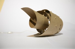
Bending Paper Lamp

Photo credit: Mara Sylvester

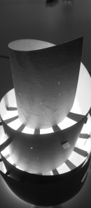
The task was to figure out a design by the basis on the technique of bending and a material that was cardboard/papper. Our design implements the concept of one-piece/self-supporting structure that could spread light creating an atmosphere for diverse kind of spaces.

We tested several kinds of material and cut more than 2 times in order to explore the characteristics and select the best for the purpose of design. Our first tests had some engraving to manage the curve but at that time paper kind of broke because it was to hard to manipulate, another issue that we had was about how to fix together by this kind of arms-structure, they just disengaged from the main body. The design of the Lamp was made on Rhino modeling software, but we started doing some tests from shapes in different kinds of paper and bending. The cutting procces using a lasser cutter machine had these characteristics. Cutting process: Speed= 60  Power=80.


At the end we selected a kind of cardboard flexible but with the strength enough to resist itself in a single piece bended using kind of sticks folded from the central piece of paper.

Also posted in Chun-Yu Lin, IC.1 Digital Fabrication, Pavel Aguilar Urquidez, Sasa Jokic | Comments closed

Milling: Curves

The Concept here was to take advantage of the linearity of the board but at the same time break the verticality using horizontal lines. Thus the curves were aligned in vertical direction while the depths were defined using the horizontal contours.

In order to maintain the uniformity in the panel, single Ball mill of diameter 12 mm was used although variation in depths were produced. The experiment here was to go against the nature of the material and see the result. Hence, the tool was designated to run horizontally even though extra effort would be added was known.

Strategy:

Tool: Round Ball mill

Diameter: 12 mm

Maximum Depth: 20mm

Time: 45 mins

Description:

The idea here was to set the design and create a surface using loft of curves in rhino. Later set contours as a distance of 8mm along the required direction. Now, instruct the tool to follow along the contour lines based on the depth.

Also posted in Farshad Mehdizadeh, IC.1 Digital Fabrication, Uncategorized | Comments closed